Control Valve Circuit Diagram Flow Control Valve Circuit Dia
3 way pneumatic valve schematic diagram Control valve schematic diagram Valves types valve globe control flow schematic open close wide rate operation use
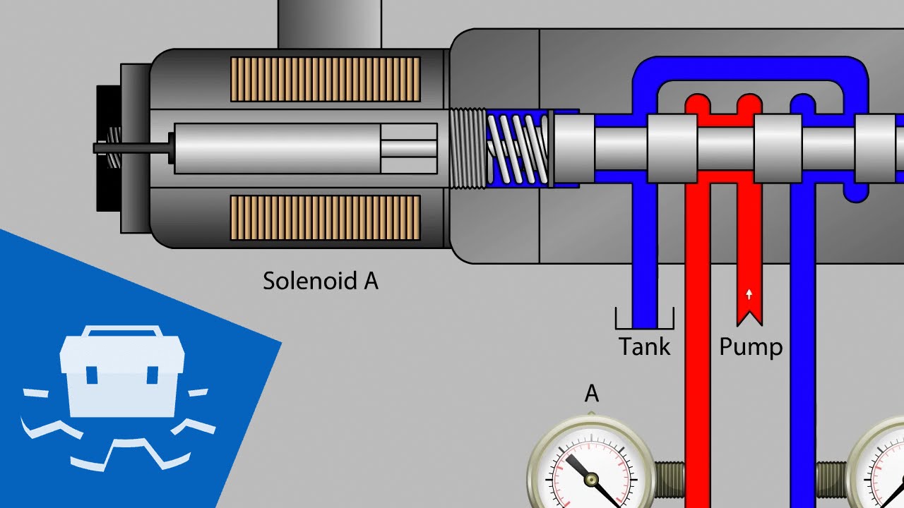
HYDRAULIC CIRCUIT DIAGRAM// 4 WAY 3 POSITION DIRECTIONAL CONTROL VALVE
Flow control valve circuit diagram A & b). 5-ports/ 3-way proportional directional control valve the Understanding the basics: control valve schematic diagram explained
Control valve
Valve positioners positioner pneumatic valves actuators principles cutawayFlow control valve circuit diagram Control valve circuit diagramValve hydraulic control diagram directional way circuit position basic.
Flow control valve schematic symbolHydraulic circuit for the valve-controlled system. Flow control valve circuit diagramElectro system actuation.

Flow control valve circuit diagram
Schematic diagram of a control valveTypes of valves Control valve schematic diagramControl valve circuit diagram.
Understanding the basics: control valve schematic diagram explainedDetented solenoid valve control circuit diagram Pneumatic cylinder check valve at james flowers blogControl valve schematic diagram.

Directional control valve circuit diagram
How flow control valves workControl valves flow hydraulic work animation valve diagram system mechanical wiring Backpressure regulating valve valves pressure back schematic limiting spring loaded illustration inlet plunger sideHydraulic flow control valve schematic.
Flow control valve circuit diagramSchematic diagram of valve control system. Detented solenoid valve control circuit diagramFlow control valve circuit diagram.
Control valve parts and functions
Valve positioners[diagram] bobcat control valve diagram Hydraulic circuit diagram// 4 way 3 position directional control valveFlow control valve circuit diagram.
Schematic of the electro-hydraulic valve actuation system.Schematic diagram of the flow control valve .


